Bench fixtures
Three procedures in this guide assume a small piece of shop-made hardware: verifying your level factor needs a meter clipped onto the signal, the PSC-1 standard condition names a 10 kΩ fixture, and a control measurement needs a loop with nothing in it. None of them is precision hardware. On the bench this app was developed on, one small box now does all three; the photographs further down are the pieces it replaced — a spare plug, a patch cable, and one resistor — and each of them still works if you would rather not build the box.
The Breakout Box
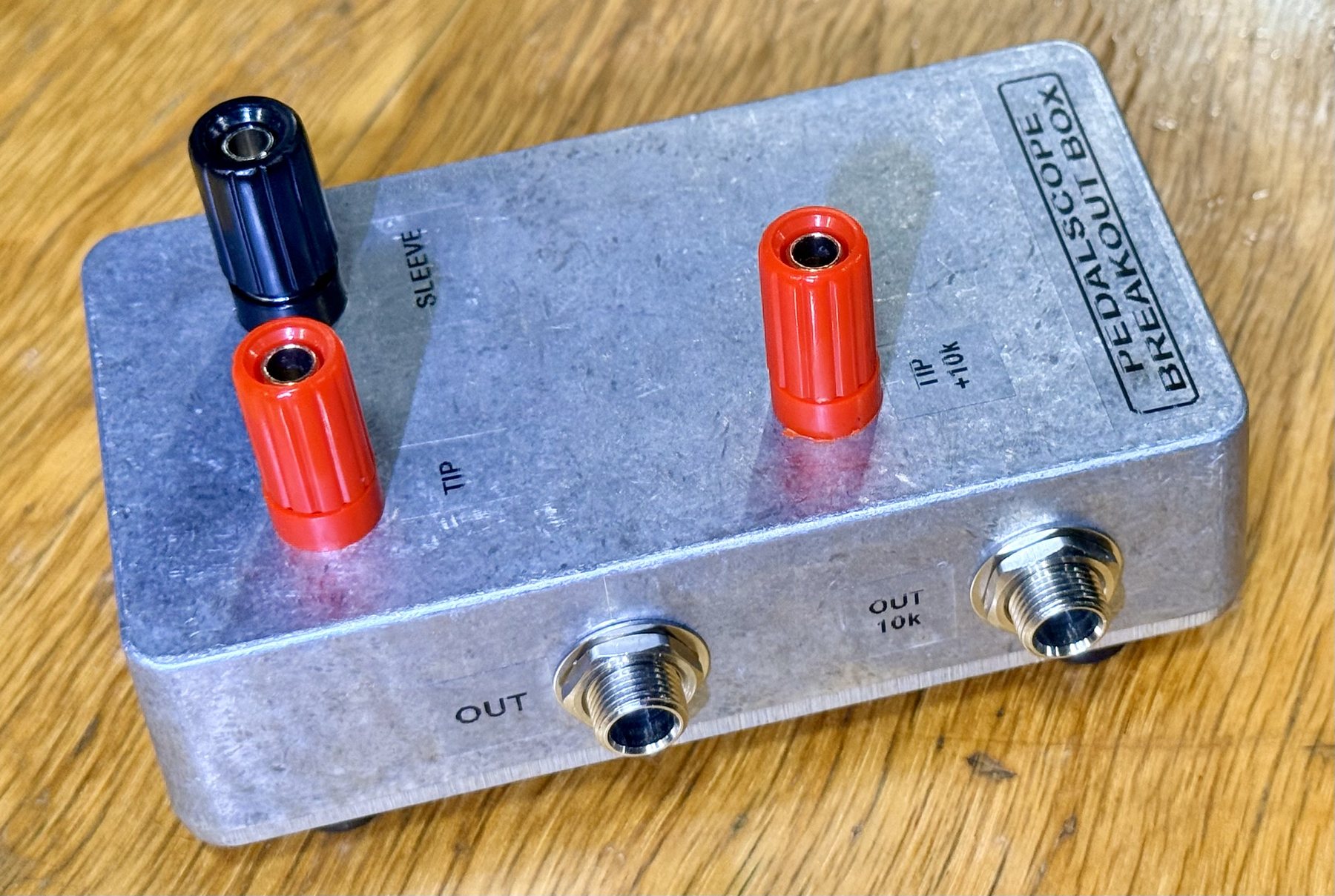
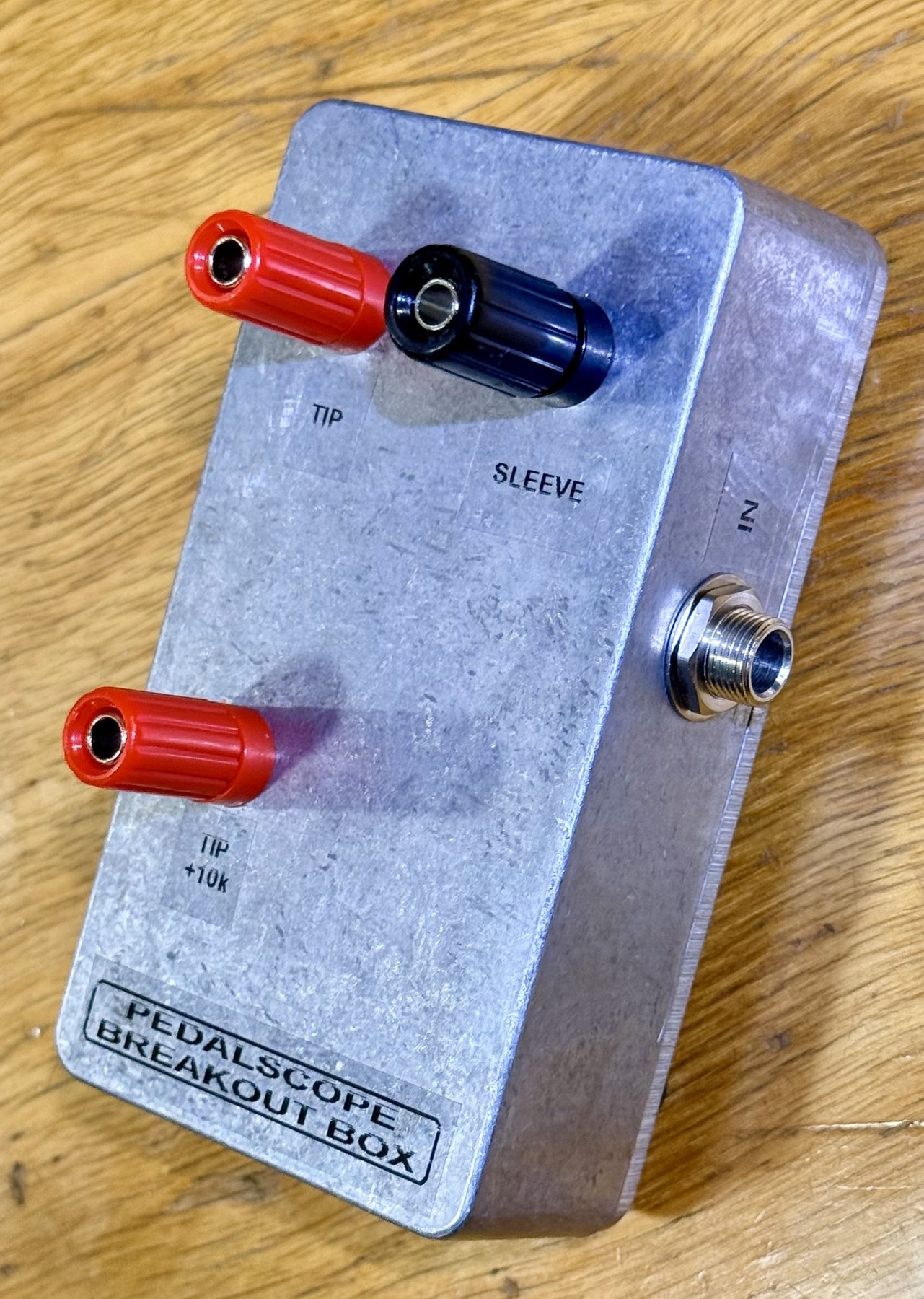
The box is a die-cast aluminium enclosure (a Hammond 1590B, the size most pedals are built in) with one ¼-inch jack on the end, marked IN, and two on the long side, marked OUT and OUT 10k. On top are three 4 mm binding posts: red TIP, black SLEEVE, and red TIP +10k. The interface’s output plugs into IN; the pedal plugs into OUT or OUT 10k; the posts take a probe.
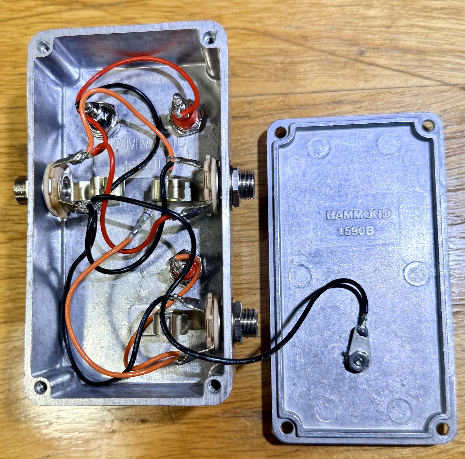
Inside it is as simple as it looks. IN’s tip goes straight to the TIP post and to OUT’s tip — a direct pass-through. IN’s tip also goes through one 10 kΩ resistor to the TIP +10k post and to OUT 10k’s tip. Every sleeve is common, to the SLEEVE post and to the enclosure, and a lead bonds the lid to that ground, so the closed box is a shield rather than a lid resting on one.
One box, three jobs — each one a procedure this page used to describe with a separate improvised part:
1. A probe point on the loop. Clip a meter or scope to TIP and SLEEVE with both plugs seated, and read the signal while the tone plays — no bare plug, no unscrewed cover, nothing that has to be undone afterwards. Black on SLEEVE, every time, so a reading taken today is comparable to one taken next month. This is where the level factor in the Reference Box’s own records was read: at the box’s posts, with the loop intact.
2. The 10 kΩ series source, on demand. Plug the pedal into
OUT 10k instead of OUT and the box is the declared
PSC-1 fixture — the same 10 kΩ, in the
same place in the chain, without soldering a resistor to a plug. TIP
+10k is the probe point after the resistor: with a short cable to the
pedal it is the node the pedal’s input actually sits on, so the drop
across the resistor is something you read rather than something you
assume. The declarations are unchanged and both still matter (see the
series fixture below): set the pedal’s SOURCE control to 10k, and
recalibrate with 10000 in the source-impedance field — moving the
pedal from OUT to OUT 10k changes what the loop measures, so it is a
recalibration, not a re-patch. Keep the cable from OUT 10k to the pedal
short: everything after the resistor is capacitance a 10 kΩ source has
to drive, and a long run there reads as treble rolloff on every record.
3. A straight pass-through for null runs. Plug the return cable into OUT with no pedal in the chain and IN → OUT is the null run’s loop — the same two cables the pedal will use, joined through the box instead of through the device, with a probe point on the join. A null run made this way is a control for the loop the pedal actually sees, cable for cable, which is how the Reference Box’s nulls were taken: box in the device position for the control, swapped for the box under test, cables untouched.
The Reference Box — the box of six switchable known circuits whose measurements the comparing measurements page walks through — is the device this box is most often plugged into. The Breakout Box’s schematic and build plan are open-source content kept beside the Reference Box’s, and travel with it.
The posts carry line-level signal between an interface and a pedal — a couple of volts at most. Never patch this box, or any of the fixtures below, into an amplifier’s speaker output: see Safety: amplifiers.
If you don’t have the box
Each of the three jobs has a cheaper substitute, and these are the pieces the bench used before the box existed. They are still valid; the box only puts them in one place.
Getting a probe onto the signal
Verifying the volts factor (see Calibration) means reading the interface’s output voltage with a meter or scope while the tone plays — which means getting two clips onto tip and sleeve without unplugging anything. Two ways, both cheap.
A bare plug
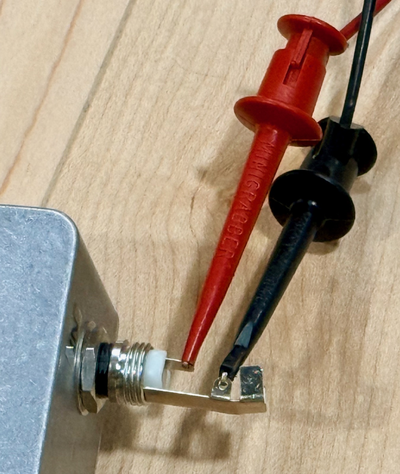
Take a ¼″ TS plug you can spare and leave the barrel cover off. Seated in a jack, its tip and sleeve solder lugs are exposed and far enough apart for two minigrabbers — red on the tip lug (the one insulated from the frame), black on the sleeve lug (the one that is the frame). Solder short leads to a second plug and you have a probe-able extension that lives permanently in the drawer.
An unscrewed cable cover
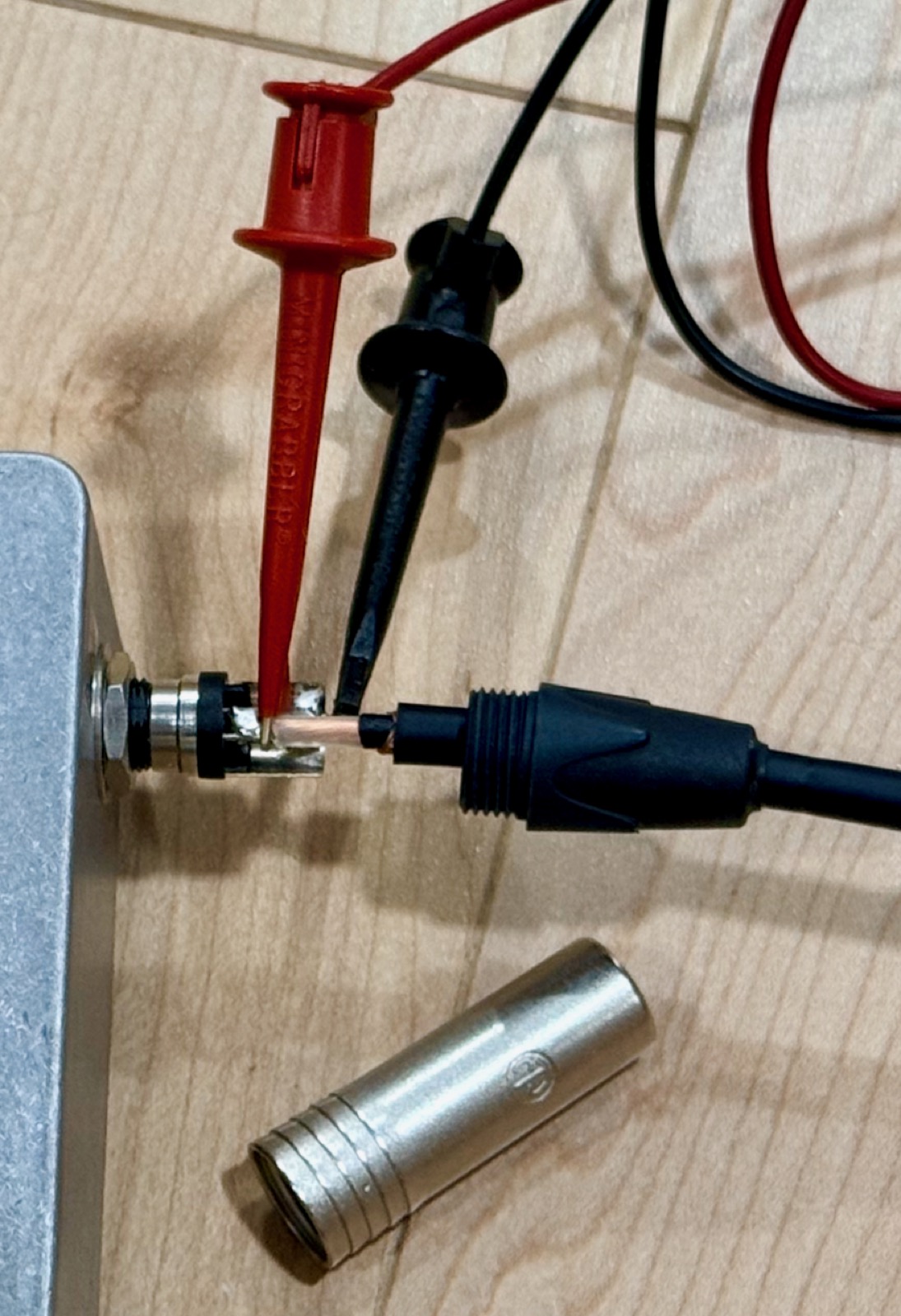
Most decent patch cables use a screw-on metal cover. Unscrew it from one plug and slide it down the cable, and you get exactly the same two lugs to clip onto — with no cable cut and no plug spent. This is the one to reach for mid-chain, where you want to probe a cable that is already in the signal path rather than substitute a different one.
Whichever you use, probe at the pedal-input end of the chain — that is the node PSC-1’s drive level is defined at — and keep the grounding consistent: black on sleeve, every time, so a reading taken today is comparable to one taken next month.
The 10 kΩ series fixture
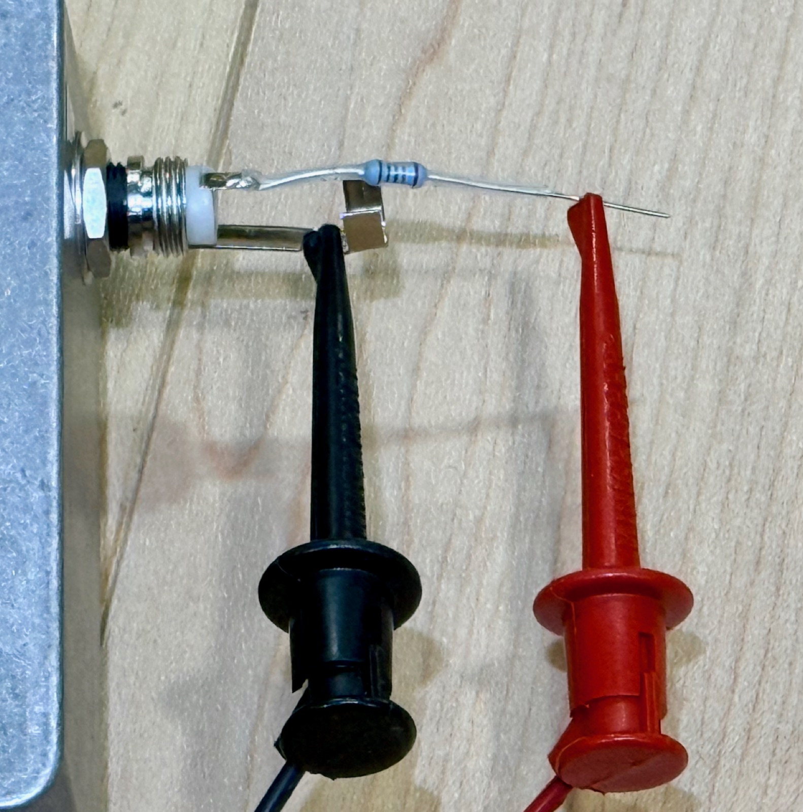
A low-input-impedance fuzz or a treble booster behaves differently when it is fed from an interface output than from a guitar pickup, because those circuits load their source (see Source impedance). A single resistor in series with the tip restores something closer to a pickup’s source impedance, and a declared 10 kΩ series resistor is the standard fixture of the PSC-1 condition.
The build is one resistor — a 10 kΩ, 1% metal film is fine — soldered to the tip lug of a bare plug, with the source clipping onto its free lead. Two things the photograph cannot show you, and both matter:
Put the resistor as close to the pedal’s input as practical. Everything downstream of it is now capacitance that a 10 kΩ source has to drive, and a few hundred picofarads of cable behind 10 kΩ is a lowpass filter inside the audio band. Mounted at the plug that goes into the pedal — as in the photo — there is essentially nothing after it. On a metre of cable after the resistor, you have quietly added a treble rolloff to every measurement and it will read as the pedal’s tone.
Declare it, or the record does not know it happened. PedalScope
models the fixture as the position of a discrete SOURCE control on
the pedal: give the pedal a control layout with a SOURCE control whose
positions include Standard (or Direct) and 10k, and set the
variant to the one you actually patched. A record measured on Standard
reads PSC-1 · 168 mV pk · direct; the same pedal measured through the
fixture reads PSC-1 · 168 mV pk · 10k fixture, and that string travels
in the badge and on every chart you export. Direct and 10 kΩ
measurements are both valid PSC-1 measurements of deliberately different
questions — which is exactly why the record has to say which one it is.
The value itself is not magic: 10 kΩ is a stated convention, not a model of any particular guitar. What makes a fixture measurement citable is that it is declared, not that the number is perfect.
The rig side says it too. The calibration you run with the fixture in
place stamps its source impedance (the field beside the volts
reference in the Calibrate step — enter 10000), and every record made
with that calibration shows “source impedance 10 kΩ” in its header and
is flagged by Compare against records made at 0 Ω. The SOURCE control is
the pedal’s declaration for the PSC-1 condition string; the calibration
stamp is the rig’s, and it is the one that survives on a record whose
pedal never had a SOURCE control. Set both. A calibration made before
the stamp existed reads “source impedance not recorded”, which is not a
claim of 0 Ω.
The null-run cable
The last fixture is the least impressive and the easiest to forget: a plain TS–TS patch cable with nothing in the middle, used to run the loop with no device in it. That is the null run — the control capture that measures what your rig and cables contribute on their own, at the same interface gain as the pedal captures it speaks for.
It earns a name here because it is a real part of the method rather than an accident of tidying up. A same-session null run is what lets the Distortion vs Level chart draw a measured floor instead of an inferred bound: whatever stands above the null curve is the pedal, and whatever the two share is the rig. Use the same cable and the same gain settings each time, and keep it with the other fixtures.